
IRB-RET2:
Retroreflective Photoeye
Installation Quickstart Guide and Best Practices
The EMX IRB-RET2 was designed with a laser-focus on the challenges faced by installers.
What was our vision?
To forge a product that not only simplifies the setup but also champions consistent performance and reliability over its lifespan.
However, as with any high-quality tool, the IRB-RET2 truly excels when installation best practices are employed.
Below, we’ve put together a QuickStart guide to assist you in tapping into the IRB-RET2’s full potential.
Step 1: wiring
Remove the back plate of the photoeye and feed the wires from the operator through the ball joint opening. The wires must enter via a UL listed watertight fitting.
Connect wires from the controller to the photoeye according to the controller’s monitoring method. Set the DIP switches SW1 and SW2 and the jumper JP1.
Shown right is a common example configuration for normally closed operation.
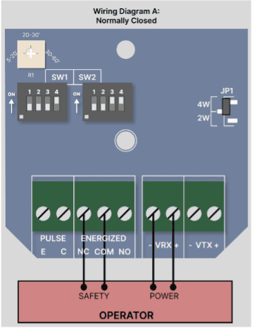
If the controller uses a different monitoring method, consult the IRB-RET 2 Instruction Manual (pp. 10-12) for more information on additional connections, JP1 jumper configuration, and/or DIP switch settings.
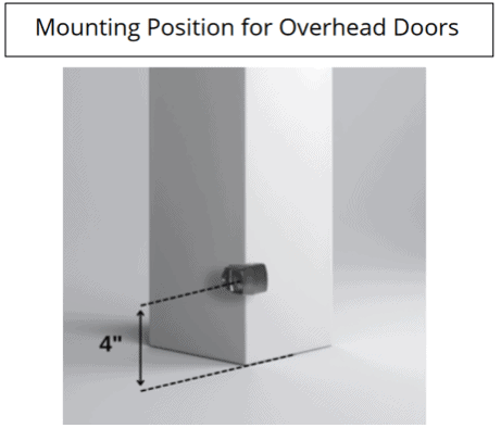
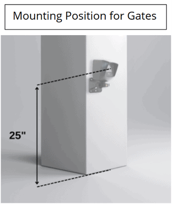
step 2: positioning and mounting
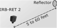
The range of the IRB-RET2 is 5’ to 60’ (1.5m-18.3m). Mount the device in a location compliant with UL 325 guidelines.
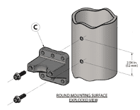
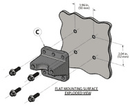
Mount the bracket clamp base (ITEM C) to the mounting surface and attach the photoeye and bracket clamp. Leave the clamp loose enough that the photoeye can be adjusted during the alignment process.
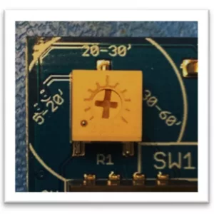
step 3: alignment
Adjust the photoeye sensitivity using potentiometer R1 on the top left of the PCB. Use the silkscreen markings as a guide based on the distance to the reflector (e.g., if the distance is 25’, then point the potentiometer dial towards 20-30’ as shown in the image).
Once the final adjustments are made, replace the back cover on the photoeye. Apply power to the photoeye and aim it towards the reflector’s planned location.
At the reflector’s planned location, move the reflector up, down, left, and right, and watch the LEDs on the photoeye. Take note of the full area that results in best alignment, about 24” in diameter. Mount the reflector in the center of the alignment zone. If the photoeye is having trouble aligning, adjust the aim of the photoeye and repeat the alignment process.
Once aligned, tighten down bracket clamp screws (ITEM B) and the set screw (ITEM A, 3/32” allen wrench needed) on the photoeye bracket.
Confirm that the system is still well aligned with a solid red LED. Place an obstruction (e.g. hand) between the photoeye and the reflector and confirm that the red LED turns off. Remove the obstruction and it will turn back on.
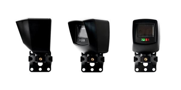
led alignment indicator
| Green LED (L) | Red LED (R) | Indicated state |
|---|---|---|
| ON | ON (solid) | Best alignment |
| ON | ON (flashing) | Partial alignment |
| ON | off | No alignment or beam obstructed |
| off | off | No power |
Check the operator control board and verify that the safety input is recognized by the operator. Test the beam with an obstruction at multiple distances to confirm proper operation. Follow the operator manufacturer’s installation instructions and safety checks to verify that the photoeye is operating properly.
For additional information including troubleshooting, consult the IRB-RET 2 Instruction Manual.
EMX INDUSTRIES INC. | 5660 TRANSPORTATION BLVD, GARFIELD HEIGHTS, OHIO 44125 | 800‑426‑9912 | © 2023 EMX INC. – ALL RIGHTS RESERVED | MADE IN THE USA