CarSense 101

Vehicle Motion Detector with Sensing Probe (Sensing Probe sold separately)

  • Easy to use and install
  • Easy upgrade or switch out to new devices
  • Quick access to controls
  • Buried sensing probe protects against potential intruders
  • Wide power supply options
  • Energy conservation

An Overview of the CarSense 101

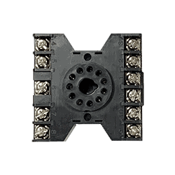
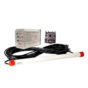
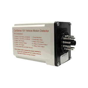
The CarSense 101 vehicle motion detector consists of a control module with a standard 11-pin connector and a sensing probe that is easily installed along a roadway. The CS101 can be seamlessly integrated with security control boards, gate and door operators.

The CS101 provides a solution for many vehicle detection challenges, including:

  • Safety – detects moving vehicles in blind areas along a driving path and actuates warning lights
  • Security – detects approaching vehicles or unauthorized movement of parked vehicles and actuates alarms, video cameras or other annunciators
  • Access control – acts as a free exit vehicle detector for gates, overhead doors and parking barriers

Features

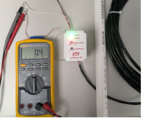
  • Controls and indicators are mounted on front panel
  • Available in 9 – 41 VDC 6 – 29 VAC
  • Low 2.5 mA standby current consumption, makes it an excellent choice for solar power applications.
  • Housed in a small, relay-type housing
  • Surge protection

Specs

Power Supply 9 – 41 VDC or 6 – 29 VAC
Power Supply Tolerance +/-20% from the power rating
Stand-by Current 2.5mA maximum
Detect Current 50mA maximum
Relay Type DPDT
Relay Rating 1A 24V DC 120V AC
Sensitivity High, Low adjustment
Off Delay 1 to 5 seconds adjustment
Control Unit Temperature Range -40° F to 170° F
Probe Temperature Range -40° F to 170° F
Power On Indicator High intensity Green LED
Detect Indicator High intensity Red LED
Sensitivity Control Continuous adjustment
Off Delay Control Continuous adjustment
Surge Protection MOV, neon and silicon protection devices
Control Unit Housing Break resistant Polycarbonate H:2.2”(55mm), W:1.6”(41mm), D:3.25”(84mm)
Connector 86CP11 11 pin connector
Probe PVC water tight housing (Length 17”, Diameter 1”) with shielded direct burial lead-in cable

LD-11B
(included)
Black, narrow profile, 11 pin socket base for DIN rail mount

PROBE-50/100
Sensing probe with 50 or 100 ft lead

HAR-11
11 position harness
3 feet of wire

LD-11
Black, wide profile, 11 pin socket base for DIN rail mount

Spec Sheet

Manual

Why does my CS-101 intermittently send an output signal when nothing should be triggering it?

There are many possible causes for this problem.

Damaged wires: Make sure there is an open circuit (OL, INF) between the black wire and shield wire, and also between the red wire and shield wire. Any other result indicates the problem is the probe.

View Image

Damaged wire test
Damaged wire test

High sensitivity: Reduce the sensitivity by turning the sensitivity dial clockwise about a quarter turn to see if this prevents the false triggers. Test to make sure the sensitivity is still high enough to trigger when a ferrous metal object is moving by the probe.

Overloaded power supply: Remove all other electronic equipment from the power supply that is powering the CS-101.

Noise in the system: Make sure the probe shield wire and earth ground are connected to pin 6 to reduce noise. Make sure there are no underground or above ground power lines, or power transformers nearby the probe since significant changes to the magnetic field around the probe can cause it to trip.

Broken sensitivity dial: Sensitivity dial should have stopping points at min and max. It should not be able to turn all the way around in a continuous rotation.

Why is my CS-101 stuck always sending an output signal and the red light is always on?

Probe resistance: Disconnect the probe wires from the controller and make sure the resistance across the red and black wires is 845-1055 ohms. A value outside this range means the probe is bad.

View Image

Damaged wire test

Damaged wires: Make sure there is an open circuit (OL, INF) between the black wire and shield wire, and also between the red wire and shield wire. Any other result indicates the problem is the probe.

View Image

Damaged wire test
Damaged wire test

Noise in the system: Make sure the probe shield wire and earth ground are connected to pin 6 to reduce noise. Ensure no underground or overhead power lines or transformers are nearby.

Why is my CS-101 stuck always sending an output signal even when the red light is off and nothing should be triggering it?

There may be a problem with the CS-101 relay.

  1. Disconnect the relay contacts (NC, COM, NO) from the operator inputs.
  2. Connect a digital multimeter to the COM (pin 3) and NO (pin 4) contacts to measure ohms.
  3. The meter should read open (OL, INF). Move a metal tool over the probe. Verify the red LED turns on and the meter reads less than 10 ohms. If the red LED turns on and the meter is still showing open, the relay is defective.
View Image

Damaged wire test

Why is my CS-101 not sending an output signal when something should be triggering it?

Vehicle moving slowly: The probe will only trigger when a vehicle is moving at least 5mph near the probe.

Low sensitivity: Increase the sensitivity dial by turning it a quarter turn counterclockwise.

Probe resistance: Disconnect the probe wires from the controller and check resistance across the red and black wires (845-1055 ohms).

View Image

Damaged wire test

Why is my CS-101 not sending an output signal even though the red light is on?

There may be a problem with the wiring or CS-101 relay.

  1. Verify you have the correct wiring from the probe to the CS-101 relay to the operator.
  2. Check both relay outputs with the following test:
    1. Disconnect the output (NC, COM, NO) from the operator inputs.
    2. Connect a digital multimeter to the COM (pin 3) and NO (pin 4) contacts to measure ohms.
    3. The meter should read open (OL, INF). Move a metal tool over the probe. Verify the red LED turns on and the meter reads less than 10 ohms. If the red LED turns on and the meter is still showing open, the relay is defective.
View Image

Damaged wire test

How do I check to make sure my probe and CS-101 controller are working?

1. Probe

Probe resistance: Disconnect the probe wires from the controller and measure resistance across the red and black wires (845-1055 ohms).

View Image

Damaged wire test

2. CS-101 Controller

  1. Disconnect the output contacts (NC, COM, NO) from the operator inputs.
  2. Connect a digital multimeter to the COM (pin 3) and NO (pin 4) contacts to measure ohms.
  3. The meter should read open (OL, INF). Move a metal tool over the probe. Verify the red LED turns on and the meter reads less than 10 ohms. If not, the relay is defective.
View Image

Damaged wire test

You may also like...

Have Any Questions ?

Have questions or need pricing on one of our products?