IRB-MON2

UNIVERSAL UL325 THRU BEAM PHOTOEYE KIT

  • Kit includes transmitter, receiver, integrated protective hoods and removable lens sunshield
  • Thru beam configuration
  • UL325 compliant
  • Four (4) monitoring interfaces
  • 115 ft. operating range
  • Easy installation and set-up
  • Compatible with many operators

PART NUMBERS:

  • EMX-1000-1: IRB-MON2 THRUBEAM PHOTOEYE KIT

IRB-MON2 PHOTOEYE OVERVIEW

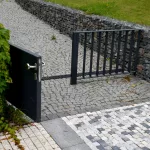
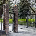
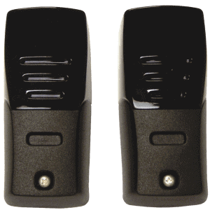
The IRB-MON2 is a monitored, weather-proof, thru beam infrared photoeye solution providing entrapment protection for doors, gates and barriers. The IRB-MON2 Safety Photo Beam is UL325 compliant and housed in an IP65 rated enclosure suitable for indoor and outdoor use.

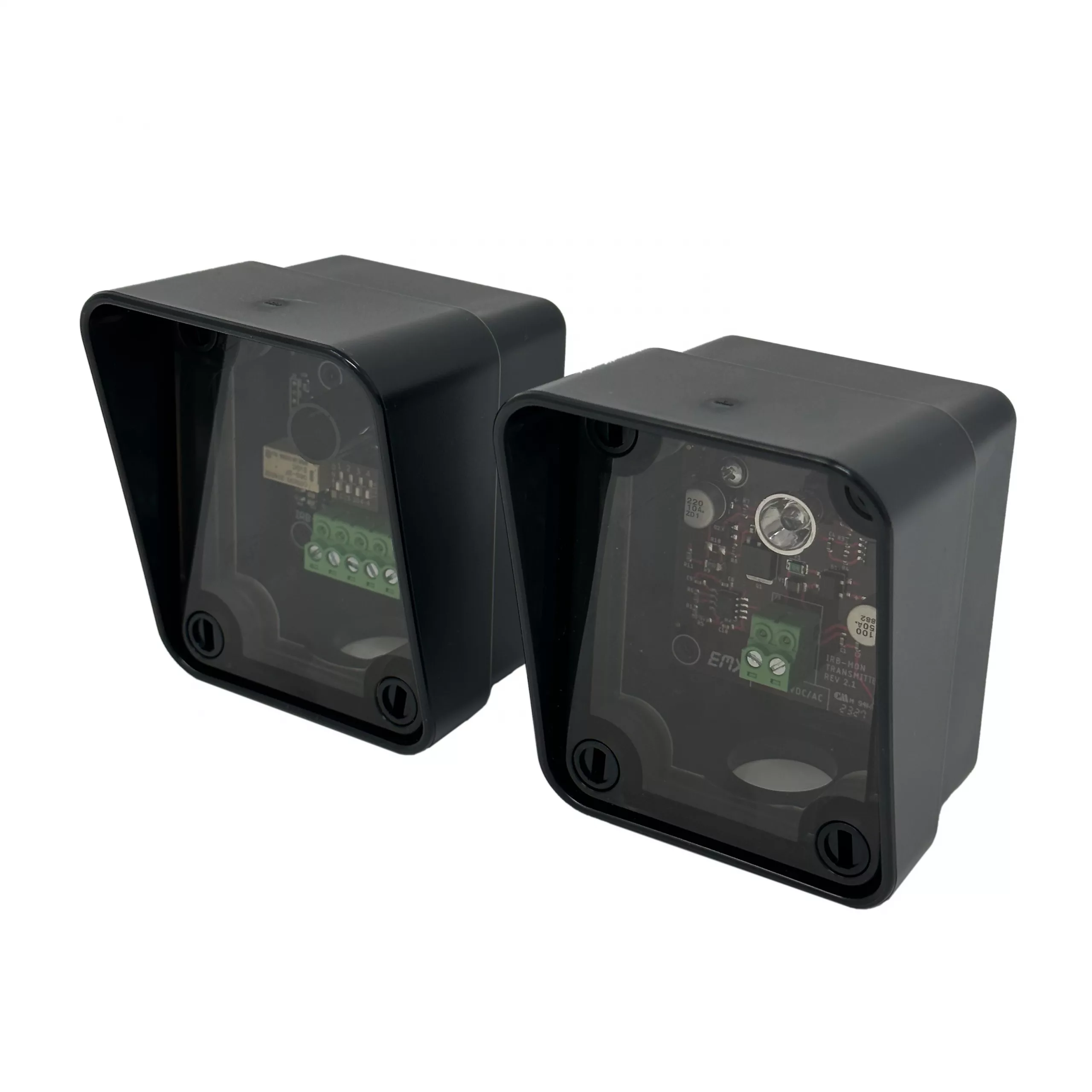
This universal UL325 thru beam photoeye can be used with a wide variety of monitored operators. Additionally, the IRB-MON2 photoeye is compatible with most non-monitored legacy products. Its robust construction minimizes fogging and false triggering to provide easy alignment.

Features

  • Enhanced version of the original IRB-MON
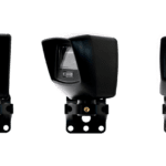
  • Advanced features in a compact design
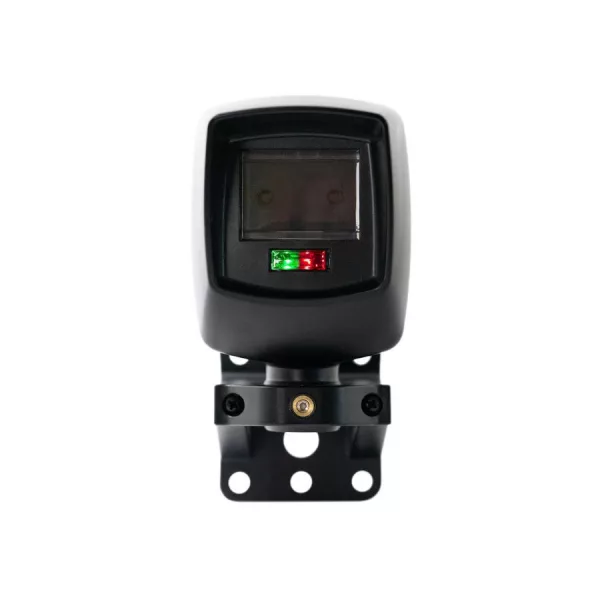
  • Integrated sensor hood for element protection
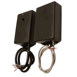
  • Removable terminal block for easy wiring
  • IRB-MON2 can be used in non-monitored applications using standard NC/NO contacts
  • Various UL325 Monitoring Methods for adaptability
  • 0.83″ (21.3 mm) Conduit Hole – large enough for 1/2 Inch NPT
  • 115 ft. Operating Range
  • Detachable Screw Terminals
  • IRB-MON2 can be used in non-monitored applications using standard NC/NO contacts

The IRB-MON2 universal UL325 thru beam photoeye has 4 monitoring interfaces:

  1. Normally closed
  2. Two-wire pulsed (2 freq)
  3. Two-wire pulsed (3 freq)
  4. 10k resistive termination

SPECS

Operating Range 5 to 115 ft (35 m)
Power 6-35 VDC, 12-24 VAC
Current (NC and 10K Monitoring Methods) 35 mA DC (when aligned and relay activated)
Current (Pulse Monitoring Methods) 15 mA
Connections “Removable” screw terminal for easy wiring
Supported Monitoring Methods 10K, 2-wire pulse, Normally Closed (power cycle)
Relay Output Configuration Form C contacts (NO, COM, NC)
Response Time <300 ms (for use in NC or 10K monitoring)
Operating Temperature -40° to 170°F (-40° to 77°C)
Dimensions (L x W x H) 3.6” (91 mm) x 2.9” (74 mm) x 2.9” (74 mm)
Conduit Hole Size (bottom of the housing) 0.83″ (21.3 mm) – large enough for 1/2 Inch NPT

Spec Sheet

Manual

How do I wire this device to my operator?

Wiring Instructions: Follow the below table to find the correct wiring diagram for your gate operator. Wiring diagrams are found in your EMX product manual. It will show the necessary wiring configuration and dipswitch settings. Check with your gate operator manual to make sure you are using the correct connection type/monitoring method. Updated as of 3/4/2025

Gate Operator EMX Diagram
Apollo/Nice B
All-O-Matic A
Autogate B
DoorKing B
FAAC A
Hy-Security A
Liftmaster B
Linear (apex) B
Max Controls A or B
PowerMaster C*
Us automatic B
Viking B

Caution: *Caution: using two wire pulse incorrectly can damage your device. Be advised to check your operator manual.

How do I make my device non-monitored?

Non-Monitored Setup: Follow diagram A, but run a wire to NO instead of NC.

My receiver is still connected to the transmitter when the beam is broken.

Sensitivity Adjustment: Turn down the sensitivity.

Multiple Transmitters: If you have multiple transmitters, make sure you are only receiving signal from the one you want to be connecting to.

My receiver has a blinking light.

Sensitivity Adjustment: Turn up the sensitivity.

Transmitter Maintenance: Make sure the transmitter is clear of debris.

Transmitter Check: A trick to check that the transmitter is functioning is to look into the transmitter lens with your phone camera. You should see a crescent or a circle of violet colored light.

I changed my dipswitch settings but nothing happened.

Power Cycle: Remove power for 15 seconds and then put it back.

You may also like...

Have Any Questions ?

Have questions or need pricing on one of our products?